SSVC0059 V2 Pro version (v 2.2.28)
Introduction.
Rectification column operation.
During boiling, the vapors rise through the rectification column and reach the reflux condenser, where they condense and flow into the selection unit. Here, some of the condensed liquid, known as phlegm, is selected as distillate, while the rest is returned to the column.
The returning phlegm flows down the column, counter-currently to the rising vapors. As the phlegm flows down, it cools and absorbs heat from the rising vapors. This process, known as reflux, concentrates the more volatile components in the upper part of the column and the less volatile components in the lower part of the column.
A temperature gradient is established along the height of the column, with the highest temperature at the bottom and the lowest temperature at the top. This temperature gradient drives the reflux process and allows for the separation of the different components in the liquid mixture.
Column stabilization before selection.
Before selecting the product, you need to let the column stabilize. This means running the column without selecting any product, so that all of the phlegm is returned to the column. This allows the column to reach a steady state, with a temperature gradient established along its height.
Once the column is stabilized, you can begin selecting the product.
Maintaining balance during rectification.
During the rectification process, it is important to maintain balance between the rate of alcohol selection and the rate of alcohol vapor replenishment from the boiler.
If alcohol is withdrawn too quickly, high-boiling impurities from the bottom of the column can rise and enter the product selection, deteriorating its quality.
To prevent this, it is necessary to maintain a certain reflux ratio, which is the ratio of the amount of phlegm returned to the column for reflux to the amount of distillate taken.
Over time, the amount of alcohol evaporated decreases. Accordingly, it is necessary to reduce the selection rate to maintain equilibrium. When the tailings (high-boiling impurities) begin to move upward, the temperature in the column rises, which is a signal to reduce the selection speed.
One way to maintain balance during rectification is to monitor the temperature in the column. A thermometer is installed at the bottom of the column to monitor the temperature increase in real time. If the temperature starts to rise, this indicates that high-boiling impurities are entering the product selection. To prevent this, reduce the selection flow speed.
Using a selection unit controller.
A selection unit controller is a device that can be used to automate the rectification process.
It can monitor the temperature in the column and adjust the selection flow speed accordingly.
This can be useful for preventing high-boiling impurities from entering the product selection and for maintaining a consistent product quality.
The main task of a selection unit controller during the collection of the hearts (the purest portion of the distillate) is to maintain a constant selection temperature. It does this by stopping the selection if the temperature rises above a specified hysteresis (a small temperature difference).
Once the temperature has returned to the set temperature, the controller will resume the selection at a reduced speed.
This algorithm is simple, reliable, and time-tested. It has been used by distillers for many years to produce high-quality spirits.
Conception.
The information presented on this page is relevant for firmware version 2.2.28. Firmware link: ssvc0059_v2_firmware.2.2.28.eng.zip
Three valves are used to select the product with the Pro version firmware for the SSVC0059 V2.
Two temperature sensors are used to control temperature.
Optionally, you can use parallel selection with all three valves at a user-specified speed.
This firmware version also allows you to finish hearts selection based on the temperature in the boiler.
The SSVC0059 V2 controller has an embedded atmospheric pressure sensor. This allows it to automatically recalculate the measured temperature value to the temperature at normal atmospheric pressure (760 mmHg).
The graphical LCD display shows all necessary information that is relevant during the process.
 firmware")
Thermo probes:
- Thermo probe 1 (TP1) in the column.
- Thermo probe 2 (TP2) in the boiler (tank).
Valves:
- Valve 1 - Heads selection valve (V1)
- Valve 2 - Hearts selection valve (V2)
- Valve 3 - Tails selection valve(V3)
Valves are normally closed.
Rectification program stages:
- Heads.
Select* heads using valve 1 and finish the stage using a timer - Hearts.
Select hearts with valve 2, control temperature in the column with TP1, and automatically decrement selection flow speed. Finish the stage when either the selection flow speed is equal to or below 0.1, or the temperature TP2 exceeds the set temperature.
Optionally, parallel tails selection with valve 3, controlled by TP2 temperature in four ranges.
Optionally, constant-speed heads selection with valve 1. - Tails.
Tail selection with valve 3. Finish the tails selection with valve 3 when TP2 exceeds the set temperature.
(This step is often skipped. You can skip it if the finishing temperature is lower than the temperature at which the "Hearts" stage ends.)
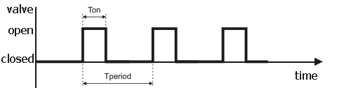
*Selection speed is adjustable by changing the ratio of valve open time to period. The valve opens periodically for a specified time, with two parameters: valve open time (Ton) and period (Tperiod). Ton is set in 0.1 s increments from 0.1 to 99.9 s, and Tperiod is set in 1 s increments from 1 to 999 s. Time is counted with 0.01 s accuracy.
How Valves Regulate Flow Speed.
Startup settings.
To open the startup settings window, hold the OK button while turning on the controller. Use the Up and Down buttons to navigate the menu items and the OK button to select and execute a menu item.
Startup settings, first screen.

The startup settings menu contains three options on the first screen:
- Beep.
If "Beep" is turned on, the controller will beep and flash the display backlight to attract attention when the "Hearts" and "Tails" stages are completed. Messages and sounds are turned off while the user is active (pressing buttons). With "Beep" turned on, you will also receive sound alarms for temperature sensor errors, stage completion alerts, and other events. - Pressure.
If "Pressure" is turned on, the controller displays atmospheric pressure. During the rectification program, the temperature is adjusted to the normal atmospheric pressure of 760 mmHg. The rectification program algorithm uses the corrected temperature. Automatic temperature correction based on atmospheric pressure allows you to maintain a stable process state, regardless of atmospheric pressure. - Mode manual/auto.
The transition mode option determines how the controller proceeds to the next stage of the distillation process. There are two transition modes:- Auto: The controller automatically proceeds to the next stage upon completion of the current stage.
- Manual: The controller notifies the user when the current stage is complete, and the user have to manually proceed to the next stage.
Startup settings, second screen.

This screen has two options:
- SIGNAL - determines what the SIGNAL output will do.
- Stabilization - allows to control the duration of the stabilization process.
SIGNAL.

The SIGNAL output is designed for experienced specialists only. It requires an external interface circuit to connect to another device. Incorrect connection of the SIGNAL output may damage the device.
The SIGNAL option can take two values: "TP error" and "TP1 control".
- TP error - The optocoupler of the SIGNAL opens when a temperature probe error occurs.
- TP1 control (default) - The optocoupler of the SIGNAL opens when the temperature of TP1 exceeds the set value. This is useful for switching heating power from full to operating.
When SIGNAL is set to "TP1 control":
- Two parameters:
- Temperature - The temperature of TP1 to control (25-100°C).
- Start at TP1 (enabled by default) - Countdown of the delayed start after TP1 exceeds the value set in the "Temperature" parameter.
- When TP1 exceeds the value specified in the "Temperature" parameter, the SIGNAL optocoupler opens (the key is closed).
- When TP1 decreases by more than 1°C below the value specified in the "Temperature" parameter, the SIGNAL optocoupler closes (the key is open).
- TP1 control begins after pressing the "Start" button on the program start screen.
- TP1 control ends with the beginning of the "Heads" stage.
- After the completion of the "Tails" stage, the SIGNAL optocoupler closes after 3 minutes.
If the "Relay on pwr on" option is disabled, the controller switches to standby mode. - The sound notification about the process finish stops after 3 minutes.
Start at TP1.

The "Start at TP1" option controls when the delayed start timer begins counting down.
- On: The delayed start timer begins counting down from the moment TP1 exceeds the temperature specified in the "Temperature" parameter for the SIGNAL option.
- Off: The delayed start timer begins counting down immediately after pressing the "Start" button on the program start screen.
Stabilization.

The Stabilization option allows you to control the duration of the stabilization process. This option is useful for the "Hearts" stage. To use the Stabilization option set the maximum time ("Time, min", up to 60 minutes) for the temperature of TP1 to return to the set temperature value. The controller will monitor the temperature of TP1. If the temperature exceeds the set threshold and the selection is stopped because of this, the controller will start a countdown. If the temperature of TP1 does not return to the selection temperature value within the set time, the controller will notify the user for 3 minutes.
Finish the step.

If "Finish the step" is enabled, the "Hearts" selection will end 3 minutes after the notification begins, unless the user intervenes.
Startup settings, third screen.

This screen has five options:
- Invert RELAY - Inverts the state of the RELAY output to turn on/off external equipment.
- Relay on pwr on - Determines when to turn on external equipment.
- Invert SIGNAL - inverts the state of the SIGNAL output.
- Backlight always - If enabled, the backlight does not turn off in standby mode.
- Continue proccess after power off - If disabled, the controller turns on in standby mode after a power loss.
Invert RELAY.

By default, the "Invert RELAY" option is disabled. In this case, closed relay contacts turn on external equipment, and open relay contacts turn it off.
If the "Invert RELAY" option is enabled, then closed relay contacts turn off external equipment, and open relay contacts turn it on.
It is important to note that the relay contacts are normally open. This means that when the controller is turned off, the relay contacts are open, regardless of the "Invert RELAY" option.
Relay on pwr on

The "Relay on pwr on" option (disabled by default) determines when to turn on external equipment. When this option is enabled, the relay turns on external equipment immediately after turning on the controller, including in standby mode This may lead to unpredictable cases after power loss, so it is strongly recommended to disable this option unless you specifically need it.
If the "Relay on pwr on" option is disabled (strongly recommended), the relay turns on external equipment only after you press the "Start" button on the program start screen.
Invert SIGNAL.

If this option is enabled, the controller inverts the state of SIGNAL (only when it is turned on).
Backlight always.

This option controls the display backlight in standby mode.
- Off: The backlight turns off when inactive.
- On: The backlight is always on.
Continue proccess after power off.

If this option is disabled (disabled by default, strongly recommended), the controller always turns on in standby mode, displaying temperature and pressure.

If the "Continue process after power off" option is enabled (disabled by default), the controller will continue the process from the saved stage after a power loss.
Standby mode.

When you turn on the controller, it enters standby mode.
The TP1 temperature is displayed in large numbers, the TP2 temperature is displayed on the right side,
and the current atmospheric pressure is displayed at the bottom of the screen.
To start the rectification program, press any button. The settings screens for the rectification program will then appear.
Rectification program settings.
Rectification program settings, first screen.

The first screen of rectification settings has six options:
- Temp. offset - adds 0.07°C when assigning hearts selection temperature.
- Close on Pause - valve 2 is closed during the pause for assigning the hearts selection temperature.
- Formula - reduces the body selection flow speed by TP2 temperature (in the boiler) according to the formula.
- Tank pressure - pressure in the boiler, mm Hg.
- TP2 offset - TP2 correction during rectification (-2.0..+2.0).
- TP Filter - ignores short-term (no more than 1 in 3 seconds) temperature surges.
Temp. offset.

Temperature offset. When the "Temp. offset" option is enabled (default), 0.07°C is added to the current temperature to set the hearts selection temperature. This option is recommended to avoid situations when the temperature does not return to the set temperature for a long time. When the temperature exceeds the set value plus hysteresis, selection stops and resumes when the temperature returns to the set level. If you use a temperature offset, the selection will resume earlier, working ahead of the curve. In this case, the hysteresis should be set to 0.07°C less than when operating without an offset. The value 0.07 was chosen because it is the closest whole number, within 0.01°C, to the resolution of the DS18B20 sensor (0.0625°C).
Close on Pause.

Close on pause: Valve 2 is closed during the pause for assigning the hearts selection temperature (the "Pause" parameter on the "2.Body. V2" screen). This option is enabled by default and recommended for additional stabilization of the column after the transition from the "Heads" to the "Hearts" stage.
Formula.

This option reduces the hearts selection flow speed based on the temperature in the boiler. If the option is enabled, the hearts selection flow speed is reduced by 6% per 1°C from the original speed.
The formula for calculating the speed is:
(6.04 - 0.06 * TP2) * <initial speed>
where TP2 is the temperature in the boiler and <initial speed> is the original hearts selection flow speed. The formula starts to apply when the temperature in the boiler reaches 84°C.
The flow speed reduction algorithm according to the formula works in addition to the decrement algorithm. If the speed calculated by the formula is lower than the current speed, the current speed is assigned the value calculated by the formula.
For example. Initial data:
- initial speed: 1/5 (1 s - valve is open, 5 s - period)
- flow speed of fully open valve: 5000 ml/h
| Temperature | Valve open, s | Bandwidth | Speed, ml | Decrease, ml |
|---|---|---|---|---|
| 84 | 1 | 20% | 1000 | |
| 85 | 0,94 | 19% | 940 | -60 |
| 86 | 0,88 | 18% | 880 | -60 |
| 87 | 0,82 | 16% | 820 | -60 |
| 88 | 0,76 | 15% | 760 | -60 |
| 89 | 0,7 | 14% | 700 | -60 |
| 90 | 0,64 | 13% | 640 | -60 |
| 91 | 0,58 | 12% | 580 | -60 |
| 92 | 0,52 | 10% | 520 | -60 |
| 93 | 0,46 | 9% | 460 | -60 |
| 94 | 0,4 | 8% | 400 | -60 |
| 95 | 0,34 | 7% | 340 | -60 |
| 96 | 0,28 | 6% | 280 | -60 |
| 97 | 0,22 | 4% | 220 | -60 |
| 98 | 0,16 | 3% | 160 | -60 |
| 99 | 0,1 | 2% | 100 | -60 |
| 100 | 0,04 | 1% | 40 | -60 |
Tank pressure.

The boiler pressure is specified in mmHg. This value is added to the current atmospheric pressure to calculate the TP2 temperature correction for pressure.
This option is useful for more accurately calculating the alcohol content of the boiling mixture in the boiler.
TP2 offset.

This option corrects the TP2 temperature during the rectification program. The correction value can be between -2.0°C and +2.0°C.
This option is useful for more accurately calculating the alcohol content of the boiling mixture in the boiler.
TP Filter.
The TP filter option filters temperature sensor surges.
It is disabled by default.
It is recommended to enable the TP filter option as a temporary solution when detecting temperature sensor surges.
However, it is important to replace the problematic sensor as soon as possible.
Enabling the option increases the sensor reading inertia by 1 second.
1.Heads. V1 - valve 1 settings, "Heads" stage.

"Heads" stage configuration. This screen configures the operation of valve 1 in the "Heads" stage.
-
Valve 1
- Valve open: The valve is open for a specified period of time.
- Period: The time between valve openings.
- If the valve open time is 30 seconds and the period is 360 seconds, the valve will open for 30 seconds every 360 seconds, or 8.33% of the time.
- If the valve open time is 10 seconds and the period is 100 seconds, the valve will open for 10 seconds every 100 seconds, or 10% of the time.
- Heads Timer - The time for heads selection. After this time, the selection of heads stops. Can be set in the range 0 to 24 hours.
- Delay - The time to wait before starting heads selection. Can be adjusted from 5 seconds to 5 hours in 1 minute increments..
The selection of heads begins at the end of the delay time, before which valve 1 is closed.
1.Export/import of settings.

On this screen, you can export settings to a file or import previously exported settings from a file.
Export
By default, exported settings are saved to the file SSVC0059.DAT.
If there is at least one file with a .DAT extension on the memory card, you have the choice to save to an existing or a new file.
New file names are formatted as NEW_<number>.DAT.
Import
You can select a settings file to import. The file mask is *.DAT. File name requirements: 8 characters or less, Latin letters only.
A maximum of 6 files are supported when exporting/importing.
2.Hearts. Valve 2 - V2 settings, "Hearts" stage.

- Valve 2: Valve open time / Period
- Valve open time: The time that valve 2 is open during each cycle.
- Period: The time between valve openings.
- Hysteresis - The maximum permitted temperature increase before the flow speed is reduced. Set by the user in the range 0.06..2.0°C.
When the TP1 temperature increases more than the hysteresis, the body selection stops and the flow speed (open valve time) decreases by the decrement amount. - Decrement - The amount by which the flow speed is reduced when the temperature increases more than hysteresis. Set by the user in the range 0..100% of the initial speed.
If the cycle is stopped due to excessive temperature, the valve opening time is reduced by the decrement value, which is set as a percentage of the "valve open" parameter. The screen displays the calculated valve opening time in seconds, accurate to 0.01 s.
When the valve open or decrement parameter is edited, the decrement value in seconds is calculated from the current values. If the valve open parameter decreases to a value below 0.1 s, the "Hearts" stage stops. -
The Hearts T pause is the delay for assigning the hearts selection temperature. It starts after transitioning to the "Hearts" stage.

During the pause, the selection is performed without temperature control. This allows the column to stabilize and allows for more accurate assignment of the hearts selection temperature. By default, the pause is 0. In this case, the sampling temperature is assigned at the time of transition to the "Hearts" stage.
* when the "Close on Pause" option is enabled, valve 2 is closed, i.e. no selection is made - Stop temp,°C - The stop temperature is the TP2 temperature (in the boiler) at which the "Hearts" stage ends. The "Hearts" stage will end when the TP2 temperature reaches this value, up to a maximum of 110°C.
2.Hearts. Valve 3 - Valve 3 settings, "Hearts" stage.

The screenshot shows an example of the Valve 3 settings for the "Hearts" stage.
The user can change the temperature range boundaries and the corresponding valve open time and period. For each temperature range, you can set the valve open time and period.
To set the flow speed of valve 3, set the valve open time and period for the corresponding temperature range. If you set the valve open time greater than zero, then valve 3 will operate at the set speed.
2.Hearts. Valve 1 - valve 1 settings, "Hearts" stage.

Valve 1 settings for parallel operation with valve V2 at the "Hearts" stage
To set valve 1 to operate in parallel with valve V2 at the "Hearts" stage, set the valve speed (open time and period).
3.Tails. Valve 3 - valve 3 settings, "Tails" stage.
Valve 3 settings at the "Tails" stage.
The Valve 3 settings for the "Tails" stage include the speed and finishing temperature at TP2 (maximum 110°C).
To start the program, click the "Start" button.
Rectification program.
Waiting TP1.

If the "Start at TP1" option is enabled in the settings, the controller will wait until the TP1 temperature exceeds the set value. You can skip this step by clicking the "Next" button.
Delayed start.

Delayed start of the selection.
The next step is the delayed start of the selection.
The minimum delayed start time is 5 seconds.
During the countdown of the remaining time, you can use the Up and Down buttons to change this time.
Pressing the OK button resets the remaining time to 5 seconds.
When the countdown ends, the "Heads" stage will begin.
The main elements of the program execution screens are shown in the figures below.
Heads.

Hearts.

Tails.

Control.
Intuitive control with three buttons.
- Up and Down buttons: Navigate through interface elements or change the value of an edited element.
- OK button: Press the on-screen button or enter the editing mode (pressing the OK button again finishes editing).
- Hold down the Down button: Display the temperature from the sensors without atmospheric pressure correction.
- Press the Up and Down buttons simultaneously: Edit the stage parameters.
- Hold down the Up button: Manually control the stage valve.
Manual valve control.

In manual valve control mode:
- OK button: Changes the valve state to open (ON) or closed (OFF).
- Up or Down buttons: Exit manual mode.
Temperature sensor error handling.
If there is an error with TP1 at the "Hearts" stage or TP2 at the "Tails" stage, the relay output will switch to the equipment shutdown state after 3 minutes if the user does not respond.
If there is an error with TP1 at the "Hearts" stage, valve 2 will close.
If there is an error with TP2 at the "Tails" stage, valve 3 will close.
Logging.
If there is a memory card in the slot, a rectification log will be recorded to a file named SSVC0059.CSV. Data is recorded once per minute.
To correctly complete recording to the file, remove the memory card after the program finishes and exits to the standby screen after 5 seconds.
Data format:
Step;Time;Target temp;Open time;Period;Current speed;Pressure;Tank pressure;TP1;TP2;TP1 correction;TP2 correction;Valve 1, s;Valve 2, s;Valve3, s;Alc;Stop;Total stops
Step: 1 - Heads, 2 - Hearts, 3 - Tails;
Time: total time since the start of program execution;
Target temp: set temperature for this stage (not relevant for the Head stage);
Open time: valve open time (valve of this stage);
Period: valve period;
Current speed: open tipe to period ratio;
Pressure: Atmosphere pressure;
Tank pressure: atmospheric pressure + pressure in the boiler;
TP1: temperature at sensor 1;
TP2: temperature at sensor 2;
TP1 correction: temperature at sensor 1 adjusted to normal atmospheric pressure;
TP2 correction: temperature at sensor 2 adjusted to normal atmospheric pressure;
Valve 1, s: total open time of valve 1 (V1) in seconds;
Valve 2, s: total open time of valve 2 (V2) in seconds;
Valve 3, s: total open time of valve 3 (V3) in seconds;
Alc: alcohol content of the boiling substance in the boiler;
Stop: selection stopped;
Total stops: total stops.
Logging is useful for choosing the optimal starting speed, which you should select to minimize the number of total stops at the end of the process.
If there are more than zero total stops, this indicates that you selected a starting speed that was too high.
The temperature during hearts selection exceeded the selection temperature plus hysteresis, which caused the hearts selection stops.
To reduce the number of total stops, try reducing the starting speed slightly for the next run. You can continue adjusting the starting speed until you have only 0 or 1 total stop at the end of the process.
We are looking for experienced reseller partners to help us sell our product in new markets. Reseller partners will receive exclusive pricing and our original product, as well as support from our dedicated team of experts. If you are interested in becoming a reseller partner, please contact us to discuss cooperation options. Our email: sales@smartmodule.ru